
This article was originally posted by Russ Tabaka and reposted here with permission from Catalytic Products International.
So you’ve reached compliance with your EPA operations permit. Your manufacturing is 100% online. Your team is happy to report that your regenerative thermal oxidizer (RTO) is fully commissioned and running better than expected. These are typical reactions to a Startup/Commissioning sequence on CPI projects. Now that the system is running and production is back to full speed the real question is this: What type of maintenance is required on the RTO? Over the next few months, we’ll be looking at the critical, yet often overlooked, requirements for keeping a quality CPI RTO online and running smoothly.
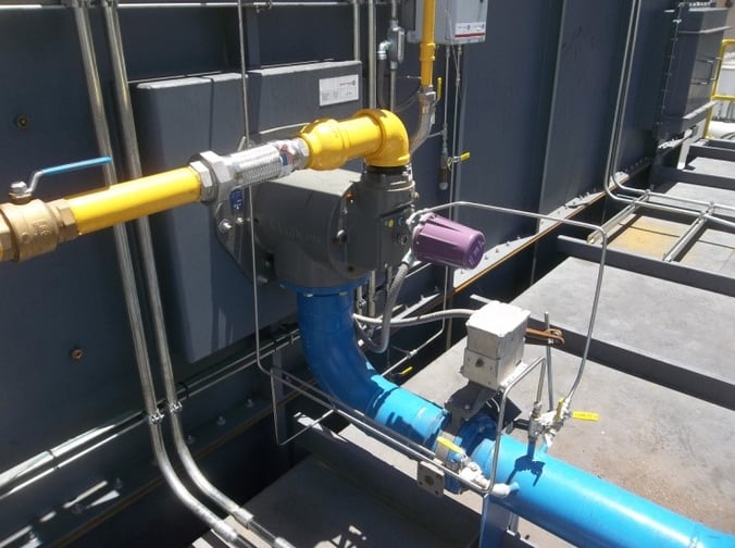
This week’s topic is burner maintenance. During the startup process, CPI Service Technicians will trim the burner to the specific customer requirements to reach the designed destruction efficiency. The details outlined below are critical to the overall operation of the burner. These small items can have major impacts on the proper operation of your RTO. In many RTO applications, CPI will provide a Kinemax style burner; however, these tips can also be applied to most external burner applications which require combustion air.
Spark Ignitor
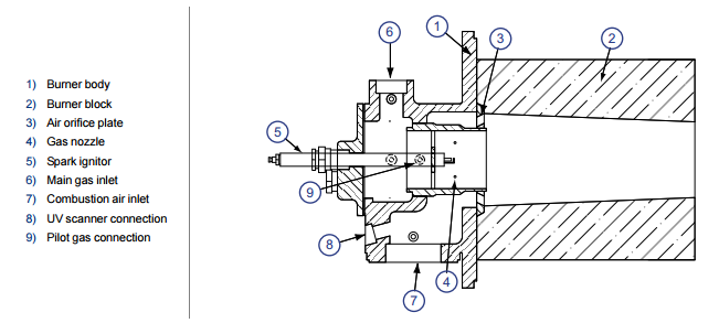
The spark ignitor (item 5 in the diagram below) stands as the ignition source for your burner once the proper mixture of combustion air and natural gas has been achieved in the burner nozzle. Many spark ignitors are made of a ceramic body, a locking bushing, and an ignitor element. Important details to follow are to verify that the spark ignitor’s insertion depth is to the specification of the burner housing.
If the ignitor is set too far back from the burner nozzle, the spark may not cause the burner to light. If the ignitor is set too deep into the housing, the burner may not light due to the mixture of gas and air dissipating in the burner nozzle downstream of the specified length per the burner data sheet. For direction on the correct spark ignitor depth, consult your CPI operations manual for a spark ignitor part number and burner application data.
Burner Actuator(s) Operation
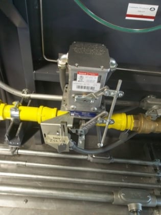
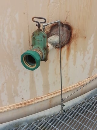
Most RTOs will be delivered with two actuators that are critical to the proper operation of the burner. One actuator is located on the combustion air piping, and the other is located on the main gas pipe line to the burner. Both actuators will operate based on a 4-20 mA signal.
Proper operation of these actuators may be controlled by the use of limit switches located on the valve body. These limits are set by the RTO’s program and will adjust the proper mixture of combustion air and natural gas to maintain the temperature set point of the combustion chamber. To verify proper operation of these actuators during a shutdown, maintenance can use a multi-meter to manually operate the valves and visually check for a loose linkage or parts requiring further adjustment (oil, tightening, etc.).

Draining Compressed Air Lines
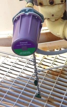
The RTO will include a UV scanner for flame detection and a sight port for personnel to physically lay eyes on the burner during operation. Both of these components are visible through chambers in the burner casting and RTO shell.
In an effort to keep these chambers clean of debris during operation, CPI will pipe compressed air from the combustion air line to a needle valve on the UV scanner assembly and to a needle valve connected to the sight port. The likelihood of these small pipes (typically 3/8”) filling with condensation is very high. To prevent any moisture build up in the compressed air line, CPI provides drip legs at the low points of these connections. These drip legs are designed to allow draining while the RTO is in operation, which can be completed on a daily inspection, if desired.
Visual Burner Flame Inspection
A true sign of burner operational issues can be discovered through a visual inspection of the flame. A proper flame will burn at a steady rate, and it will be blue in color with a hint of yellow at the tips. Signs of poor burner operation include pulsation in the flame, a flame that is orange in color, or an unsteady flame pattern. If any of these signs occur, maintenance can refer to the CPI operations manual for target flows on combustion air and natural gas. If these flows are not able to be reached, the next step can be to trouble shoot the actuators on the combustion air and natural gas.